
Abstract
The impedance response of a Li electrode enclosed in a pouch cell casing is compared with the response of the same electrode in coin cell and Swagelok cell casing. A significant difference is observed in the high-to-medium-frequency part of the response. The difference is explained using a simple equivalent circuit. The explanation is further confirmed by a series of experiments in which the electrodes are either transferred from one cell type to the other, or the surface area of lithium metal electrode and contactingmetal from the cell casing is varied. Six different electrolytes are used to demonstrate the generality of the phenomenon due to (inadvertent) wetting of the stainless steel case in coin cells and Swagelok cells; such wetting results in distortion of the main impedance arc, which may even split into two separate arcs. A similar situation can occur in pouch cells when a significant surface area of the metal used for contacting the lithium metal electrode is in the direct electrochemical field of the cell. Solutions to this problem are briefly presented.
Export citation and abstract BibTeX RIS

This is an open access article distributed under the terms of the Creative Commons Attribution 4.0 License (CC BY, http://creativecommons.org/licenses/by/4.0/), which permits unrestricted reuse of the work in any medium, provided the original work is properly cited.
Electrochemical impedance spectroscopy (EIS) is an important electrochemical tool that can give valuable insight into various phenomena occurring in batteries. 1–3 In the case of the Li metal anode cell, it is commonly used to study the properties and growth of the passive layer. The passive layer is formed on the Li metal surface due to its high reactivity with organic electrolytes. Its composition and morphology depend on the electrolyte used. The layer forms a barrier to electron transport and further electrolyte-Li metal interactions. In contrast, the layer conducts lithium ions and is also called solid electrolyte interphase (SEI). 4–7
In order to perform reliable and reproducible measurements with EIS, some effort must be put into the cell design intended for EIS measurements. Theoretically, cells with three electrodes are preferred as they provide the most accurate and direct electrochemical information about the electrode under study. 8 However, many researchers prefer configurations similar to those used for battery performance testing, such as two parallel electrodes separated by the thinnest possible electrolyte-soaked separator. Such a configuration makes it difficult to position a third (reference) electrode, and few successful impedance studies have been published using such a setup. 9
Another way to use a battery-preferred design and still obtain relatively high quality electrochemical information about a given battery electrode is to make symmetrical cells, i.e., cells with two electrodes of interest that are as identical as possible, separated in turn by a thin electrolyte-impregnated separator. 7,10,11 Such symmetrical cells can be conveniently made using one of the three most common casings (housings): the so-called pouch cell casing, the coin cell casing, and the Swagelok cell casing.
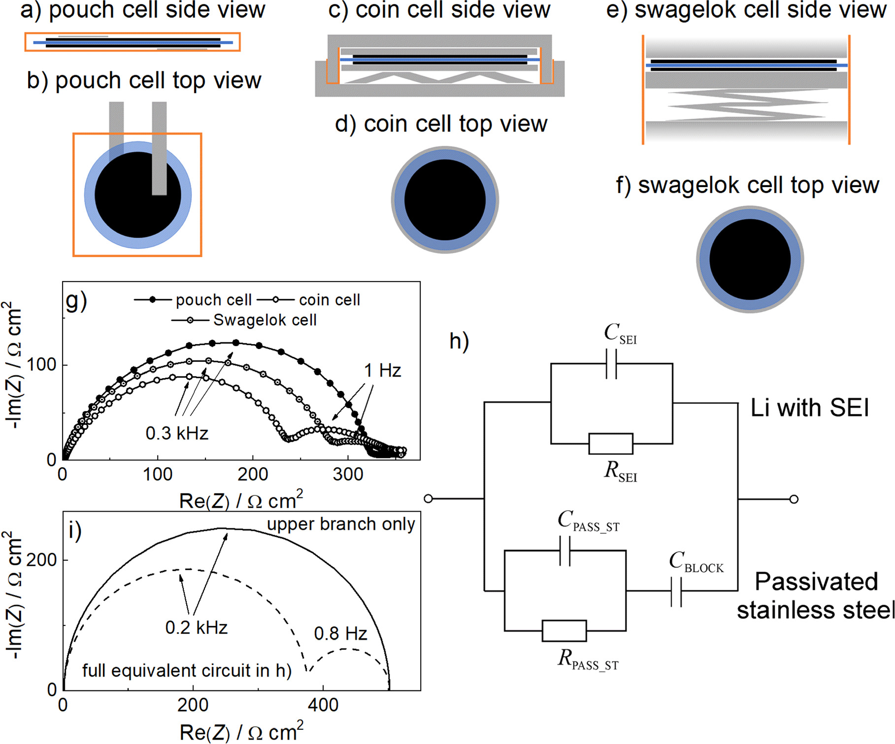
Pouch cell casings (Figs. 1a and 1b) consist of a plastic casing (triplex foil) that can be heat-sealed. Contact between the electrodes and the potentiostat/galvanostat is established by heat-sealing a strip of metal (tab) into the pouch. This tab is either an extension of the current collector that holds the electrode material or, if the electrode is free-standing, a strip of other non-reactive metal (copper, aluminium, nickel, etc). Proper contact between the electrodes and the separator containing the electrolyte is ensured by applying pressure on the outside of the pouch cell. Pouch cell casings are limited to electrolytes that are compatible with the inner plastic coating, and are usually not reusable because they must be cut open, losing some of the pouch plastic. Most importantly, they are usually vacuum sealed, which is a disadvantage when using volatile solvents for the electrolyte preparation.

Figure 1. (a)–(f) top down and side views of different cell casings used in the study. Black represents the electrodes and blue represents the separator. Grey represents metallic parts of the casings and orange represents plastic parts. Pouch cell design depicts free-standing electrodes. (g) Stabilised impedance response of Li||Li symmetrical cells in pouch, coin and Swagelok cell casings. For all cells, the Li metal anode was used as received and the separator consisted of one layer of Celgard 2320. 20 μl of LP40 electrolyte was used for the cell assembly. The lithium electrode area was 2 cm2 for the Pouch cell and the maximum possible area for the metal cases—1.54 cm2 for the Coin cell and 1.13 cm2 for the Swagelok cell. For comparability, the Nyquist plots are drawn in Ω cm2 units. (h) Simplified equivalent circuit describing the occurrence of two main arcs in coin cell. The upper branch describes the transport of lithium through SEI on metallic lithium (represented by RSEI and CSEI) whereas the lower branch, represented by RPASS_ST and CPASS_ST, describes the transport of Li-ions through passivated stainless steel. CBLOCK represents the blocking of Li-ions at the stainless steel surface. In pouch cell, the bottom branch does not exist, resulting in a single arc due to RSEI and CSEI. (i) Simulated impedance responses for symmetrical Li-Li cells in pouch and coin cell casings. The following values of the elements were used: RSEI = 500 Ω cm2, CSEI = 2 10–6 F cm−2, RPASS_ST = 1500 Ω cm2, CPASS_ST = 10–7 F cm−2 and CBLOCK = 10–4 F cm−2. Note that for the pouch cell only the top two elements were used for simulation.
Download figure:
Standard image High-resolution imageThe parts of the coin cell casing (Figs. 1c and 1d) are commercially available as battery manufacturing parts and are made of corrosion-resistant stainless steel. Airtightness is established by a plastic gasket between the positive and negative coin cell cases, which are sealed by mechanical deformation under pressure. There is a fixed amount of space available in the sealed coin cell casing, which is filled with a stainless steel spring for good contact and stainless steel spacers when the electrodes/separator stack is too thin to fill the entire available void regions in the cell pan. Since there is some empty space in the coin cells, an additional amount of electrolyte is added during assembly to compensate for any losses in the casing.
The Swagelok casing (Figs. 1e and 1f) is made with modified commercial Swagelok stainless steel tube fittings in which the fitting body is symmetrical and fits two nuts. These hold two stainless steel pistons that serve as contact points for each of the electrodes. The electrodes/separator stack is placed between the two pistons along with a spacer and spring to ensure good contact. To avoid short circuits, the body is either made of plastic or a non-conductive plastic is placed inside the metal body around the piston-cell-piston stack. Ferrules are used to ensure the cell is air-tight. Similar to coin cells, Swagelok cells have a void next to the spring, but are fully reusable.
It is expected that the proper use of any of the major battery cell designs - pouch, coin, or Swagelok - will result in a more or less identical EIS response for a given electrode under study. However, here we show that small inconsistencies that can occur in everyday cell assembly can lead to significant variations in impedance response, especially when using the coin cell and Swagelok cell configurations. We demonstrate such variations using the example of a metallic Li electrode in combination with several different electrolytes. We explain the measured spectra with a simple equivalent circuit and confirm the main hypothesis of the model through a series of systematic experiments with different cell configurations.
Experimental
All cells were prepared in an MBRAUN glovebox with controlled atmosphere (oxygen and water content below 1 ppm). The Li metal electrodes were punched from a Li metal strip (FMC, 110 μm thickness) without pretreatment. In this setup, a native SEI layer is present on the Li metal electrode. We chose to leave this layer on the electrodes because previous studies in our laboratory have shown that the impedance response is more stable over time, while at the same time the physicochemical parameters of the SEI are in a similar range as obtained in cells with scratched Li metal electrodes after stabilization. The cell was constructed by stacking one Li metal electrode (different surface sizes as indicated in each measurement), a layer of Celgard 2320 separator, and the second symmetrical Li metal electrode on top. Due to poor wetting of the separator with LP30 electrolyte, the Celgard separator was replaced by a glass fiber separator (GF-A, Whatman) in the cell where this electrolyte was used. The GF-A separator is thicker than the Celgard 2320 (260 μm vs 20 μm) and has different porosity and tortuosity. Although transport through the separator is expected to be different due to the difference in properties, this does not significantly complicate the analyzes performed, as the study focuses mainly on the shape and magnitude of impedance contributions in the 20 kHz to 0.1 Hz range, thus excluding the contributions from the separator.
A sufficient amount of the selected electrolyte was added to ensure good wetting (20 μl for 2 cm2 Celgard separator and 70 μl for 2 cm2 glass fiber separator). The cells were packaged in three different casings - pouch cells, coin cells, and Swagelok cells. The pouch cell housing consisted of a triplex pouch cell (PE 90 μm/Al 10 μm/PET 20 μm) with two Ni or Cu contacts inserted into the pouch cell in the laboratory. These cells were heat-sealed at low vacuum in a vacuum sealer in the glovebox. The CR2032 coin cell casing was crimped using a manual crimping tool (Hohsen Corporation). Swagelok Stainless steel fittings with PTFE ferrules and Mylar foil added to the fitting body were used to prevent short circuits.
When the electrode stack was transferred to another casing, the cells were placed in the glovebox, the pouch cell was opened with scissors, and the coin cells were opened with a de-crimping tool (Hohsen Corporation). After opening the previous casing, the electrode stack was transferred to another casing. When the electrode stack was transferred from the coin cell casing to the pouch cell casing, the stainless steel spacers that provide adequate pressure in the coin cell were transferred along with the stack. Namely, due to the adhesion of lithium metal to stainless steel, we couldn't remove the spacers without damaging the electrodes, so we opted for a joint transfer. In some cases, additional electrolyte was added to the cell during transfer to a new casing.
The behavior of various lithium electrolytes was tested: 1 M LiPF6 in EC:DEC 1:1 (v:v) (LP40, Elyte innovations), 1 M LiPF6 in EC:EMC 3:7 (v:v) (LP57, Elyte innovations), 1 M LiPF6 in EC:DMC 1:1 (v:v) (LP30, Sigma-Aldrich) commercial electrolytes and 1 M LiTFSI in TEGDME:DOL 1:1 (v:v), 1 M LiTFSI in DME:DOL 1:1 (v:v), 1 M LiTFSI in TFEE:DOL 1:1 (v:v) electrolytes, which were prepared in the laboratory. EC stands for ethylene carbonate, DEC diethyl carbonate, EMC ethyl methyl carbonate, DMC dimethyl carbonate, TFSI bis(trifluoromethanesulfonyl)imide, TEGDME tetraethylene glycol dimethyl ether, DOL dioxolane, DME dimethoxyethane and TFEE for 1,2-(1,1,2,2-tetrafluoroethoxy)ethane). Electrolyte preparation was performed from previously dried solvents in a multistep process involving use of molecular sieves, K/Na alloying, and distillation as described in in Ref. 12. The final water content was checked by Karl-Fischer titration (Mettler Toledo, C20) in the glovebox. The LiTFSI salt (Sigma Aldrich) was dried under vacuum at 140 °C for 24 h before use. The electrolyte was mixed in volumetric flasks to ensure the correct salt concentration. The water content in LP30, LP57, LP40 and 1 M LiTFSI in TFEE:DOL 1:1 (v:v) was below 1 ppm. In 1 M LiTFSI in TEGDME:DOL 1: 1 (v:v) the water content was 1 ppm and in 1 M LiTFSI in DME:DOL 1:1 (v:v) 18 ppm.
Electrochemical impedance spectroscopy measurements on the cells were performed using a Bio-Logic VMP3 potentiostat/galvanostat. The frequency range was between 1 MHz and 1 mHz and the potential amplitude was 10 mV (rms). Since the impedance feature attributed to the passive layer in Li||Li cells changes significantly in the first few days after cell assembly, several replicates of the spectra were measured on freshly assembled cells at OCV to ensure that the growth is stabilised before the cells were transferred to another cell housing. This was done in order to ensure that any differences in impedance spectra observed after cell casing change was due to the difference in housing and not the change in passive layer properties due to its growth. The same measurement settings were used on the cells after switching between housings.
X-ray photoelectron spectroscopy (XPS) measurements were performed using PHI Versa Probe III AD (Physical Electronics, Chanhassen, U.S.A.) equipped with a monochromatic Al-Kα1 X-ray source. The base pressure of the device was approximately 6 × 10⁻⁸ Pa. Spectra were acquired with an X-ray power of 50 W at 15 kV and a beam spot size of 200 μm at an X-ray incidence and a peel angle of 45°. The area scan mode was used to increase the measured surface area of the sample to 1000 μm2. Samples were mounted on non-conductive double-sided Scotch-3M adhesive tape ("floating" conditions), and PHI a dual charge neutralization system was used to prevent differential charging of the non-conductive surface films. High-resolution spectra of Li 1 s were acquired with at least 70 scans at a transit energy of 55 eV and a step of 0.05 eV. Spectra were acquired using PHI SmartSoft-XPS V.3.2.1 software and analyzed using PHI MultyPack V.9.9.2. A random carbon impurity was used as a charge reference for XPS spectra so that the C–C/C–H component of the simultaneously acquired high-resolution C 1 s peak was shifted to a binding energy of 284.8 eV. No peak fitting was performed because the weight of the analysis was on identifying the presence of Li 1 s on the sample surfaces.
Results and Discussion
Recently we published a detailed study 7 on the impedance response of symmetrical lithium metal cells, explaining the different impedance contributions. All experiments for the study were performed by assembling cells in pouch cell casing. When we tried to repeat and further upgrade parts of this extensive study on coin cells, we found a very systematic and quite significant difference in the main contributions of the impedance spectrum (Fig. 1g). In particular, the pouch cell typically exhibited a large impedance arc (250–500 Ωcm2) with a peak frequency of about 0.1–0.3 kHz, while the contributions at lower frequencies were all small and merged together (with a total contribution of up to 50 Ωcm2). According to the general impedance model for passivated lithium, 7,13,14 the 0.1–0.3 kHz arc is due to the migration of Li+ ions through a thin (a few nm) compact passive layer directly on the lithium electrode surface. The smaller contributions at lower frequencies are due to diffusion in the porous layers present in the cell. In the simplest symmetric Li–Li cell configuration, there are only two types of porous layers: (i) the porous part of the solid electrolyte interphase (SEI), which grows on top of the compact SEI layer and has a typical thickness on the order of 100 nm, and (ii) the electrolyte-filled separator between both Li electrodes. The characteristic frequencies of these diffusion contributions vary depending on the porosity, tortuosity, and thickness of the porous SEI and separator. In the case of the tested combination of electrolyte and separator (20 μm thick in our case), the peak frequencies of the diffusion arcs were 10 Hz and 0.1 Hz for the porous SEI and separator, respectively. The response for the pouch cell shown in Fig. 1g is in agreement with this model and also with some previous measurements, 7,15 although the low-frequency contributions are not well resolved.
By contrast, in the case where the cell was assembled in the coin cell casing, the measured impedance spectrum showed an approximately 30%–40% smaller high-frequency arc (150–300 Ωcm2) compared to the response of pouch cell, although the peak frequency was still within the 0.1–0.3 kHz peak frequency range (Fig. 1g). Very importantly, the typical spectrum also exhibits an additional low- frequency arc with a peak frequency of about 1 Hz and a resistance in the range of 100 Ωcm2. A similar spectrum is obtained if the cell is assembled in the Swagelok casing with a slightly larger high-frequency arc and a smaller low-frequency arc in the same frequency range. While the change in the size of the high-frequency arc could be due to slightly different SEI growth in a different cell (different temperature, specific glovebox atmosphere, aging of electrolyte, different pressure, etc), the appearance of a well-defined and rather large 1 Hz arc is quite surprising. At least in our laboratory, an arc with such characteristics has never been measured on symmetrical Li metal electrode cells assembled in the pouch cell casing. Note that the electrode material in the coin cells, the Swagelok cells and the pouch cells came from the same lithium metal ribbon and the cells were assembled at the same time.
In trying to understand the different impedance response of the symmetric Li-Li cell, it is important to recognize that the total impedance has a very similar value in all configurations, i.e. about 350 Ω cm2 (see Fig. 1g). It appears that the large arc in the pouch cell configuration has been split into two smaller arcs in the coin and Swagelok cells. Such a split could suggest that there are two parallel pathways for mobile ions in coin or Swagelok cells rather than just one, as would be typical for pouch cells. For example, in a coin or Swagelok cell, if the electrolyte is in contact with both the Li metal and the stainless steel case, there will be two parallel pathways for the Li-ions. Such a situation could be conceptually described with a very simple equivalent circuit as shown in Fig. 1h. The upper branch describes the transport of Li-ions through SEI on lithium (represented by RSEI and CSEI), whereas the lower branch, represented by RPASS_ST and CPASS_ST, describes the transport of Li-ions through passivated stainless steel. Since Li-ions react readily with metallic lithium, there is no particular resistance to charge transfer in the upper branch (in other words, the contribution of charge transfer resistance is assumed to be very small and is not seen in the present spectra). Conversely, the Li-ions are blocked when they hit the stainless steel surface (hence the CBLOCK element in the lower branch). For the pouch cell, the general equivalent circuit in Fig. 1h is simplified because there is obviously no stainless steel case. Therefore, only the upper branch with the RSEI and CSEI elements is sufficient for a rough description of the Li electrode in the pouch cell configuration at high and medium frequencies.
The model in Figs. 1h and 1i explains not only the splitting of the high frequency arc into two arcs (splitting one path into two for Li-ions), but also why the total impedance should be the same for both cell configurations. The total impedance is similar to the situation that occurs under dc current conditions. The model clearly shows that current can only flow through the RSEI element under dc conditions (i.e., no dc current can flow through the lower branch of Fig. 1h). Now, if the SEI resistance is the same in both cells, the low-frequency impedance should also be the same and correspond to the RSEI. It should be noted that in this analysis we only discuss the changes in the high frequency region of the spectra and neglect the rather small impedance features in the very low frequency part of the impedance response which are due to the diffusion processes.
To confirm the main hypothesis of the split impedance response in the stainless steel cell configuration, we performed several experiments in which we transferred the electrodes between different casings. For this purpose, cells as identical as possible were prepared in both pouch cell and coin cell casings as the two limiting cases. Their impedance response was measured for several days to ensure stabilisation of the passive layer growth. Then the cells were transferred into the glovebox and their casing changed. This essentially meant that we opened the pouch cell, took out the Li|separator|Li stack without interfering with the Li passive layer (the separator was never peeled away from any of the electrodes), and packed it inside a fresh coin cell casing. Similarly, the coin cell was opened and the electrode stack was transferred to a new pouch cell casing. In the latter case, stainless steel (SS) spacers originally used to ensure sufficient pressure and contact in the coin cell were transferred along with the Li|separator|Li stack, so that the actual stack transferred was SS spacer|Li|separator|Li|SS spacer. This was done because any procedure that attempted to remove the spacers resulted in damage to the lithium electrodes.
When the cell was transferred from the coin cell casing to the pouch cell casing, the two separated arcs (due to two Li paths) merged back into one (Fig. 2b), reflecting only one path in the pouch cell configuration, notwithstanding the fact that the stainless steel spacers were transferred along with the lithium electrodes and separator. It should be noted, however, that the stainless steel spacers on which the Li metal electrodes are placed represent only a small portion of the total available stainless steel surface area in the coin cell casing.

Figure 2. Comparison of stabilised impedance responses of symmetrical Li||Li cells in different casings. For all cells, 1.54 cm2 Li metal anodes were punched out of the Li foil and used as purchased and the separator consisted of one layer of Celgard 2320. 20 μl of LP40 electrolyte was used for assembly of the initial cells. Unless otherwise noted, no additional electrolyte was added when the cell was transferred between different casings: (a) Comparison of impedance spectra of symmetrical lithium cells when assembled in a pouch cell or coin cell casing. (b) Comparison of impedance spectra of lithium cells before and after transfer from a coin cell casing to a pouch cell casing. Note that the stainless steel spacers on both outer sides of the cell stack were also transferred to the pouch cell, as we could not remove them from the lithium electrodes without damaging them. (c) Comparison of impedance spectra of a lithium cell before and after transfer from pouch cell casing to a coin cell casing. (d) Comparison of the impedance spectra of a lithium cell before and after transfer from pouch cell to coin cell casing, in which case an additional 40 μl electrolyte was added to the coin cell casing before crimping.
Download figure:
Standard image High-resolution imageMoreover, the transfer of the electrode stack from the pouch cell casing to the coin cell casing did not result in arc splitting (Fig. 2c, as we might expect based on the proposed model. Nevertheless, there is an important difference in the amount of electrolyte present in the cell when we compare freshly assembled coin cells and coin cells assembled from stacks transferred from pouch cells. This is because although the exact pore volume of the separator can be calculated and accounted for, an excess of electrolyte is usually added during initial cell assembly. This is done to compensate for any losses during the actual assembly and during the growth of passive layer on the electrodes. This essentially means that when a fresh cell is assembled, the electrolyte can leak out of the Li|separator|Li stack and wet the surrounding cell casing. When the cell is transferred from the pouch cell to the coin cell casing, this excess electrolyte appears to remain on the removed pouch cell foil and only the electrolyte trapped in the separator pores is transferred. Thus, essentially no wetting of the stainless steel casing with electrolyte occurs when we transfer a stack from a pouch cell casing, at least not in the procedure we used in this study. This is a reasonable explanation for the lack of splitting into two impedance arcs in the coin cell configuration in Fig. 2c.
An obvious upgrade of the experiment shown in Fig. 2c is the use of additional electrolyte during the transfer of the cells from the pouch to the coin cell casing. Specifically, 40 μl of electrolyte was added along the edges of the electrode stack after it was transferred from the pouch cell to the coin cell casing. EIS measurement of the cell with the added electrolyte actually revealed two arcs (Fig. 2d) - due to a split of one into two Li paths, as expected from the proposed model.
The impedance response of cells prepared in coin cell casings and pouch cell casings with several different commonly used Li metal anode electrolytes was measured to determine if this additional impedance feature is a general phenomenon. As shown in Fig. 3, the same ≈1 Hz-arc appeared in cells assembled in coin cell casings for all electrolytes tested, ranging from glyme based (1 M LiTFSI in TEGDME:DOL 1:1 (v:v) and 1 M LiTFdifferentSI in DME:DOL 1:1 (v:v)) to carbonate solvent-based electrolytes (LP57, LP30, and previously also LP40) to fluorinated ether solvent-based electrolytes (1 M LiTFSI in TFEE:DOL 1:1 v:v). This arc did not occur when the cell was assembled and packed into the pouch cell casing.

Figure 3. Comparison of the stabilised impedance responses of Li||Li symmetrical cells in coin cell and pouch cell casings. The separator consisted of one layer of Celgard 2320 and 20 μl of electrolyte, except for the LP30 electrolyte, where 70 μl and GF-A separator was used for cell assembly. For all cells, 1.54 cm2 Li metal anodes were used. The spectra are normalised to the surface size of the lithium metal electrodes. (a) 1 M LiTFSI in TEGDME:DOL 1:1 (v:v) electrolyte, (b) 1 M LiTFSI in DME:DOL 1:1 (v:v) electrolyte, (c) LP57 electrolyte, (d) LP30 electrolyte, (e) 1 M LiTFSI in TFEE:DOL 1:1 (v:v) electrolyte.
Download figure:
Standard image High-resolution imageWith LP30 electrolyte, the Celgard separator must be replaced with the glass fiber separator because the LP30 electrolyte does not wet the Celgard separator. Changing the separator properties (thickness, effective diffusion coefficient) changes the transport through the separator, which affects the two separator-dependent impedance contributions—the migration resistance at high frequencies (resistive intercept) and the diffusion resistance at low frequencies. A larger diffusion contribution is the most likely reason for the distortion of the low frequency range of the spectra for the LP30 electrolyte (Fig. 3d). In addition, the glass fiber separator is more compressible than the Celgard separator, suggesting that a larger amount of electrolyte is displaced into the cell housing after compression and sealing. This could lead to a more significant second arc in the impedance spectra of the coin cell casing (Fig. 3d).
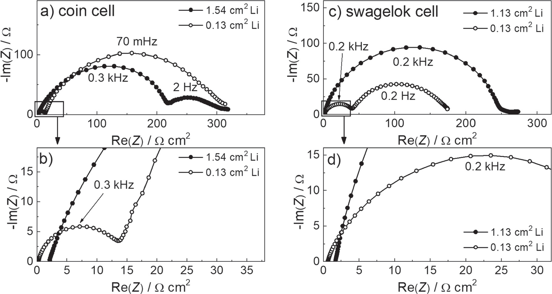
The model in Fig. 1h suggests that Li+ ion can interact with both lithium metal electrode and the metal casing of the cell. This essentially describes a mixed potential situation for Li and stainless steel. The electrochemical response of such a system is determined by the ratio of the active surface area of the two metals. Changing the relative surface sizes of lithium vs stainless steel would therefore predictably change the impedance response of the cell. To further confirm the hypothesis that the stainless steel casing affects the impedance response of the symmetric Li||Li cell in both the coin cell and Swagelok cell casing, we constructed Li||Li cells in which the Li metal surface area was decreased which, in turn, increased the wetted stainless steel surface area. For this situation, the model predicts a decrease in the resistance of the high-frequency arc while its peak frequency remains in a similar range. The resistance of the low-frequency arc will increase with a decrease in its peak frequency. On the other hand, if the hypothesis is false and the stainless steel case is not active in the electrochemical processes, the shape and magnitude of the impedance spectrum, normalized to the area of the Li metal electrode, should be identical for the larger and smaller Li electrodes. Only one difference should be visible—the resistance intercept of the cells should be the same in the non-normalized spectra, which in turn means that the larger electrodes should have a larger resistance intercept in the surface normalized impedance spectra. As shown in Fig. 4, this prediction of the stainless steel activity was confirmed by the measured spectra in both the coin cell casing and Swagelok cell casing. Decreasing the size of the Li metal electrodes resulted in a decrease in the high-frequency arc and an increase in the medium-frequency arc. The peak frequency of the former remained the same while the peak frequency of the latter decreased, and the larger the arc, the more so. Note that the spectrum of the larger Li metal electrode cell assembled in the Swagelok casing for this experiment did not exhibit a large mid-frequency arc, as measured previously and shown in Fig. 1g. We attribute this to a different degree of electrolyte wetting of the stainless steel casing. For the coin cell casing, the size of the Li electrodes is 1.54 cm2, the size of the spacers is 2 cm2 and the coin cell cup is slightly more than that. This means that the ratio between the non-covered stainless steel spacer and the Li surface size is about 1:3. This ratio is even greater when we consider the spring and coin cell cups. With Swagelok, the Li electrode size is 1.13 cm2 and the piston size is 1.22 cm2. This results in a 1:12 ratio between the available stainless steel and Li surface area. In Swagelok cells, the electrolyte could also come into contact with the spring, while most of the body of the Swagelok cells used in this experiment is protected with Mylar foil. The measured difference between the coin cell casing and the Swagelok cell casing suggests that the Swagelok cell casing is slightly better optimised to avoid the interference effects studied when the electrode is used near its maximum size.

Figure 4. Comparison of stabilised impedance responses of symmetrical Li||Li cells in coin cell and Swagelok cell casings, where the size of the Li metal electrodes was varied as specified on the figures. The separator consisted of one layer of Celgard 2320 and 20 μl of LP40 electrolyte was used for the initial cell assembly. The spectra are normalised to the surface size of the lithium metal electrodes. (a) and (b) show full spectra and magnification of the high frequency range for the coin cell tests, respectively and (c) and (d) show full spectra and magnification of the high frequency range for the swagelok cell tests, respectively.
Download figure:
Standard image High-resolution imageIn addition, we wanted to investigate whether a similar situation could occur in the pouch cell casing due to wetting of the metal tabs by the electrolyte. For this purpose, pouch cells with contact strips of different geometry were constructed. In the pre-assembly of pouch cells in our laboratory, the metal contact strips are usually narrow (3–4 mm) and embedded into the pouch in parallel to each other and a few mm apart (Fig. 1b). This is a different situation from the coin cell or Swagelok cell, where the contacting stainless steel surfaces of the working and the counter electrodes are superimposed (Figs. 1d and 1f) and are directly in the electric field generated between the working and counter electrodes during the measurement. In order to reproduce the impedance spectrum with double arcs for pouch cells, we tried to i) increase the surface area of the contact strip superimposed with the separator and ii) increase the surface area of the contact strip within the electric field occurring during the measurement. For this purpose, metal strips of different widths were arranged perpendicular to each other during the pre-assembly of the pouch cell casings. Strips of different widths were used (3 mm, 9 mm, 27 mm), which means that 9 mm2, 81 mm2 or 729 mm2 surface area of the contact strips were placed directly on one strip. The size of Li metal electrodes was kept identical and small (4 mm diameter, 0.13 cm2) with a thin Celgard separator placed in the middle to avoid contact between the electrodes or contact strips.
Significant differences between cells were measured in this experiment. Figures 5d and 5e show spectra measured on Li||Li cells with reduced Li metal anode size and different widths of Ni metal contact strips. As the cross-sectional area of the metal strips increased, the spectra followed the same response predicted and measured in the coin cells and Swagelok cells in Fig. 4. As the width of the contact strip increased, the high-frequency arc decreased and the low-frequency arc increased. The change in the size of the resistive section (Fig. 5e) is also evident, which is due to the fact that the total active electrode area changes when we consider the change in the size of the contact strips. The same experiment was repeated with Cu metal contact strips. As shown in Figs. 5f and 5g, the results were the same for this cell setup, indicating that the effect occurs regardless of the most commonly used metal strips.
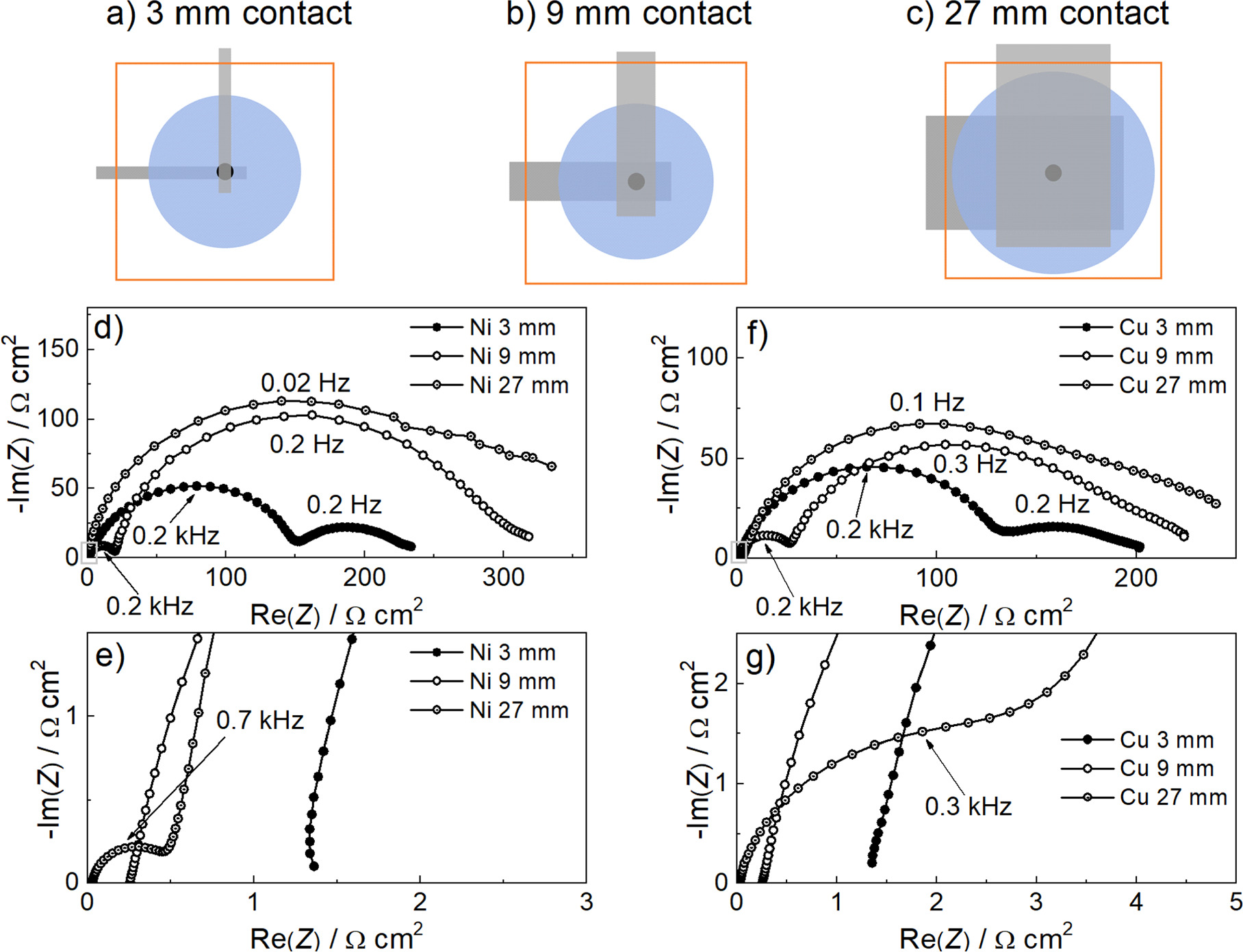
Figure 5. (a)–(c) Top views of the different cell casings used in the study. Black represents the electrodes and blue represents the separator. Grey represents the metal strips used for contacting and orange represents the plastic parts of the casing. (d)–(g) Stabilised impedance responses of symmetrical Li||Li cells in pouch cell casings where the width of the perpendicular contacting strips was varied. The Li metal electrodes were 0.13 cm2 in size and a sufficient amount of LP40 electrolyte was used to wet the Celgard separator. The spectra are normalised to the surface size of the lithium metal electrodes: (d) variation of the spectra when the width of the Ni metal contact strips is varied, (e) magnification of the high frequency range of the spectra in (d). (f) Variation of the spectra when the width of the Cu metal contact strips is varied, (g) zoom- in of the high frequency range of the spectra in (f).
Download figure:
Standard image High-resolution imageThe equivalent circuit in Fig. 1h indicates that a passive film forms on the surface of the metal casing/tab. This film must allow Li+ ions to migrate through it (elements RPASS_ST and CPASS_ST) before the Li+ ion is stopped at the metal casing surface, where no charge transfer reaction takes place (CBLOCK). To further support the hypothesis of a Li+-conducting passive layer formation, we measured XPS spectra at the surface of the metal casing/tab. We compared the surface species between cell casings used to measure Li||Li cell impedance and casings of cells with only the electrolyte-wetted separator, without the Li metal, confined between the spacers (coin cells) or tabs (pouch cells). Samples were harvested from the cells, washed with DOL and dried before analysis by X-ray photoelectron spectrometry as described in the experimental section. Coin cell casing parts were compared to Ni and Cu tabs harvested from pouch cells with larger tab surface areas (Fig. 5).
Figure 6 shows high resolution Li 1 s XPS spectra. For the coin cell stainless steel casings (Figs. 6a and 6b, Li species were detected in the Li metal cells (Fig. 6b, peak position of 55.7 eV is marked with a reference line), while we could not determine beyond doubt whether Li species are present or not in pure electrolyte cells because the position of the Li-1s peak overlaps with the Fe-3p peak (Fig. 6a; 52.25 eV for Fe, 55 eV for FeCO3, 55.55 eV for Fe2O3 and 55.6 eV for FeOOH). For the Cu and Ni tabs, the presence of Li-containing species was again confirmed in samples obtained from Li metal cells (Fig. 6d, 55.5 eV and f, 55.7 eV), while no Li species were detected in the electrolyte-only cells (Figs. 6c and 6e). In the Ni contact obtained from the cell without Li metal, Ni 3p peak was also detected at around 67.5 eV. These results further support our hypothesis, since we expected to find Li containing surface species on the samples obtained from Li metal cells and no Li species in cells where the casing came in contact with only the electrolyte (note that the LP40 electrolyte employed contains Li salt in the form of LiPF6).

Figure 6. Li 1 s XPS spectra of metal casing samples surface: coin cell stainless steel spacer surface spectra from cells where (a) the casing was in contact with the electrolyte only and (b) from cells containing Li metal electrodes. Cu tab contacts from pouch cells where (c) the casing was in contact with the electrolyte only and (d) from cells containing Li metal electrodes. Ni tab contacts from (e) pouch cells where the casing was in contact with the electrolyte only and (f) from cells containing Li metal electrodes. All cells were assembled using LP40 electrolyte. The spectra were shifted to set the C 1 s peak to 284.8 eV energy. * marks the position of Fe 3p peaks and # the position of Ni 3p peak.
Download figure:
Standard image High-resolution image
Conclusions
It has been shown experimentally that in some cases of practical interest, the impedance response of the same electrode in a coin cell or Swagelok cell configuration can be significantly different compared to a pouch cell configuration. The difference occurs when the electrolyte wets both the electrode under study and the metal case in stainless steel based casings. This simultaneous wetting creates two pathways for active ions (Li-ions in our case), which can change the shape of some impedance features. In our particular case—a passivated Li electrode—the simultaneous wetting of the Li electrode and the stainless steel case caused the main impedance arc to split into two arcs, the sum of their resistances matching the initial main impedance arc size. The extent of the impedance spectrum change is dependent on the wetted surface area of the metal casing and can be explained by a simple equivalent circuit.
Although the present study is limited to the metallic Li electrode, it must be emphasised that in most cases where both the electrode under study and another conductive surface (e.g., the cell casing) are in contact with the same electrolyte, a significant change in impedance behavior can be expected. This effect is avoided by using a non-metallic casing (pouch cell casing) together with a limited area of contact strips, ideally arranged parallel and far apart. This design of the cell casing avoids a large portion of the surface of the metallic casing entering the direct electric field of the cell.
Acknowledgments
The work was financially supported by Slovenian Research Agency ARRS (research project Z2-4465 and core programme funding P2-0393 and P2-0423).