3.1. Corrosion Products
To confirm the testing conditions also control groups with synthetic chloride-ions-enriched medium-synthetic saltwater (3.5% NaCl) were performed, which provided similar results of evolution and presence of corrosion products, for both CHT and DCT sample groups. However, the major difference compared to natural seawater was that less intense signals of corrosion products were observed for the synthetic one. In order to enhance the corrosion and to emphasize the differences between the two treatment groups (CHT and DCT) natural seawater was selected. The first set of specimens (control group) was exposed to chloride-ions-enriched medium at room temperature (CHT/DCT), aimed at verifying the observations from our previous studies. The XRD data showed that generally the corrosion products after 1 and 7 days exposure (
Figure 1a) are similar for both heat treatments (CHT and DCT). The main identified phases on the surface of all tested samples are mainly calcium carbonate (CaCO
3), halite (NaCl), iron as matrix (Fe), carbides, goethite (α-FeO(OH);
Figure 1b), lepidocrocite (γ-FeO(OH);
Figure 1c), magnetite (Fe
3O
4;
Figure 1d) and green rust (GR I and GR II;
Figure 1e). In our previous study [
13], the presence of other oxides was also confirmed, but they are not relevant to this study due to their lower volumetric presence within the surface. The observation of GR I+II also confirmed our previous findings that GR I+II is predominantly present on DCT samples, on which, later in time, magnetite (Fe
3O
4) is formed. It is suggested that GR is formed due to the presence of newly formed anions (NO
3−, SO
42− and Cl
+) that compensate the pre-existing ammonium cations (NH
4+). The main sources of nitrogen for GR for both heat treatment groups are suggested to be ions presence in chloride-ions-enriched medium and the metallic surface of AISI M35. In order to observe dynamics of nitrogen and other alloying elements (Co, Cr, Fe, V, W) in correlation with GR I+II and magnetite, which could act as the base underlying corrosion products (denoted as passive film), the samples with 1 day exposure in chloride-ions-enriched medium were selected for further study. Samples exposed for 7 days develop extended presence of other corrosion products that obscure the underlying initial corrosion layers relevant for this research.
3.2. Characterization of Layers
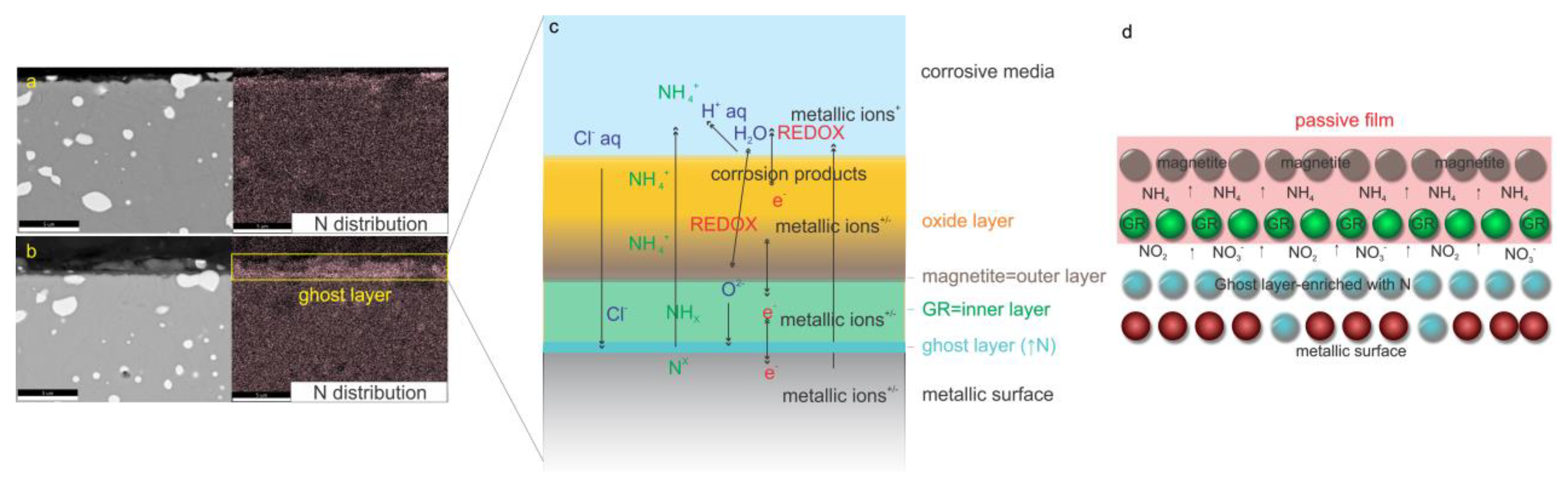
The characterization of layers (oxide layer, passive film and modified layer (ghost layer)) for both heat-treated samples (CHT and DCT) after 1 day exposure was investigated by SEM/EDX and SEM-FIB techniques in combination with XRD data and supplementary ToF-SIMS technique. The SEM/EDX-FIB analysis provided insight into the dynamics of selected alloying elements (Cr, Fe, V, W, Mo), whereas Co is excluded due to its homogenous distribution in both samples. The cross-section of CHT sample revealed that beside O, also Cr, Fe, Mo, W and V act as the main elements within the surface interphase between the metallic surface and corrosive environment, presented in
Supplementary Material 3. In the DCT sample, similar results were obtained (
Supplementary Material 3) with one major difference. In the DCT sample, a layer enriched with N and depleted of other elements, previously dubbed the “ghost layer” [
35] is formed between the metallic surface and the oxide layer. The passive film, which is correlated with the improved corrosion resistance (
Supplementary Material 1), is suggested to be enriched with N-dissolved species and acts as the inhibitor for the GR I+II growth in DCT samples and, later, magnetite (
Figure 2a,d). This phenomenon (passive film induced by DCT) is observed in correlation to DCT and corrosion properties of high-alloyed ferrous alloys for the first time. In addition to this layer, the specific development of overlaying oxide layer (partly part of passive film) is also found, at which the first inner layer is determined to be magnetite and afterwards the outer layer is composed of other oxide/hydroxide species that are also present for CHT sample. In addition, in the DCT sample minor depletion of alloying elements is observed, which is explained to originate from the protection barrier formed by the passive film as presented in
Figure 2c,d.
3.3. ToF-SIMS Surface Analyses
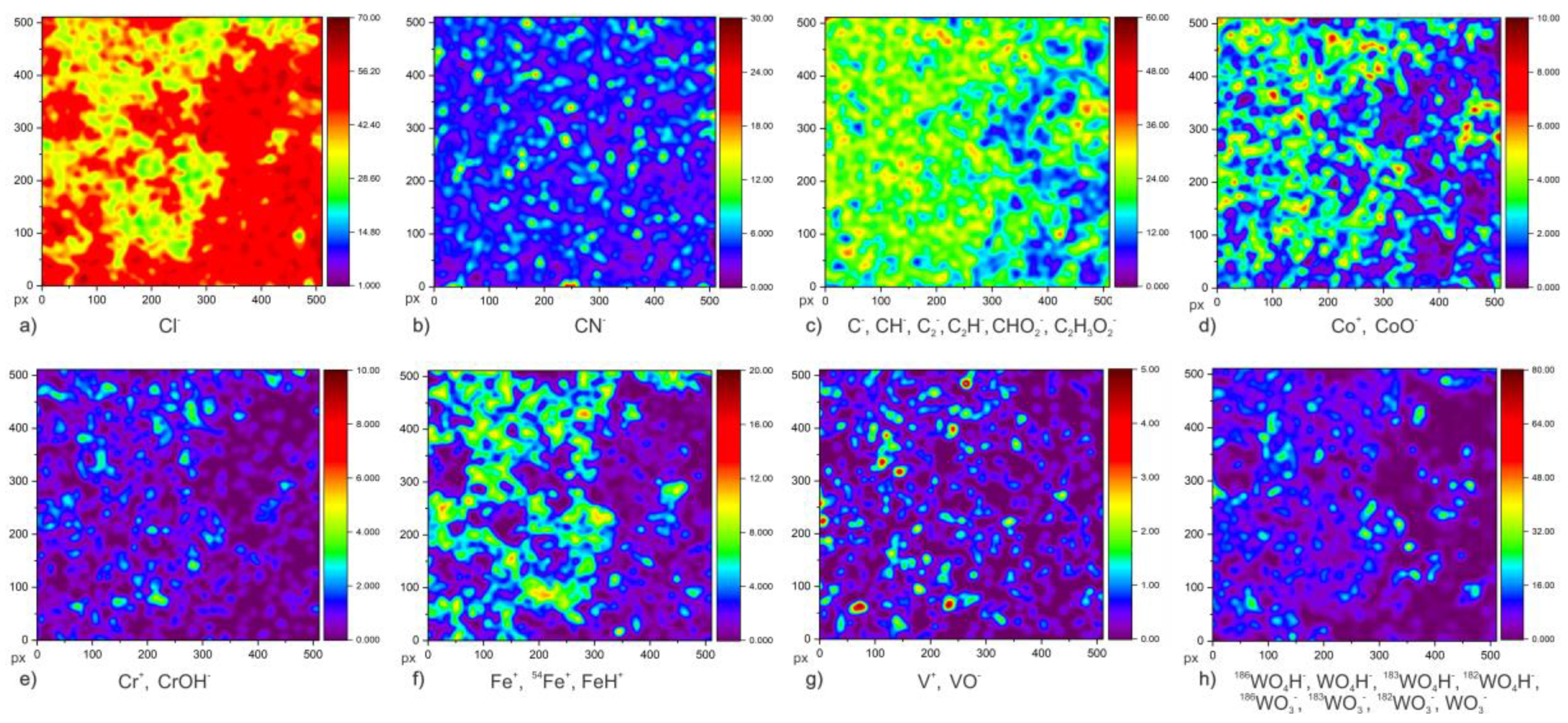
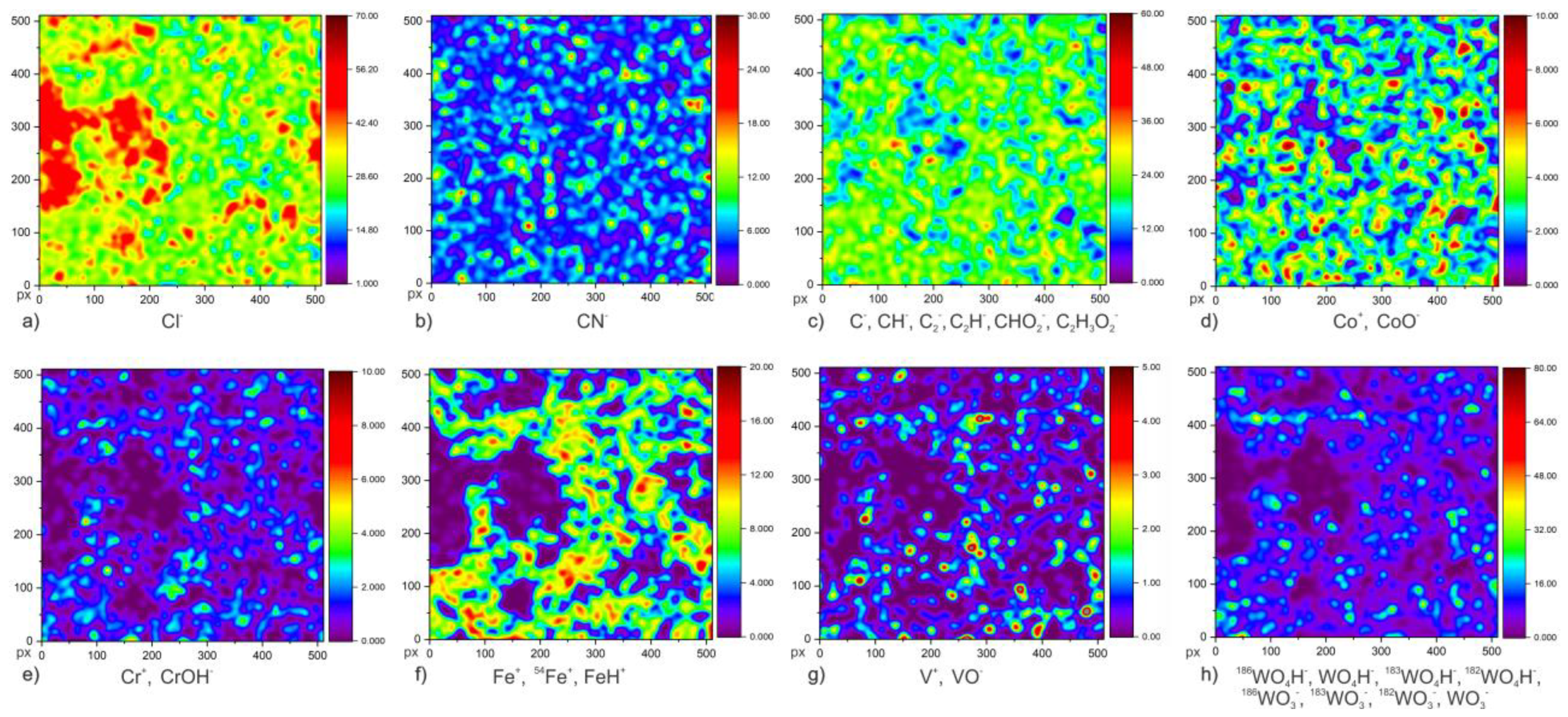
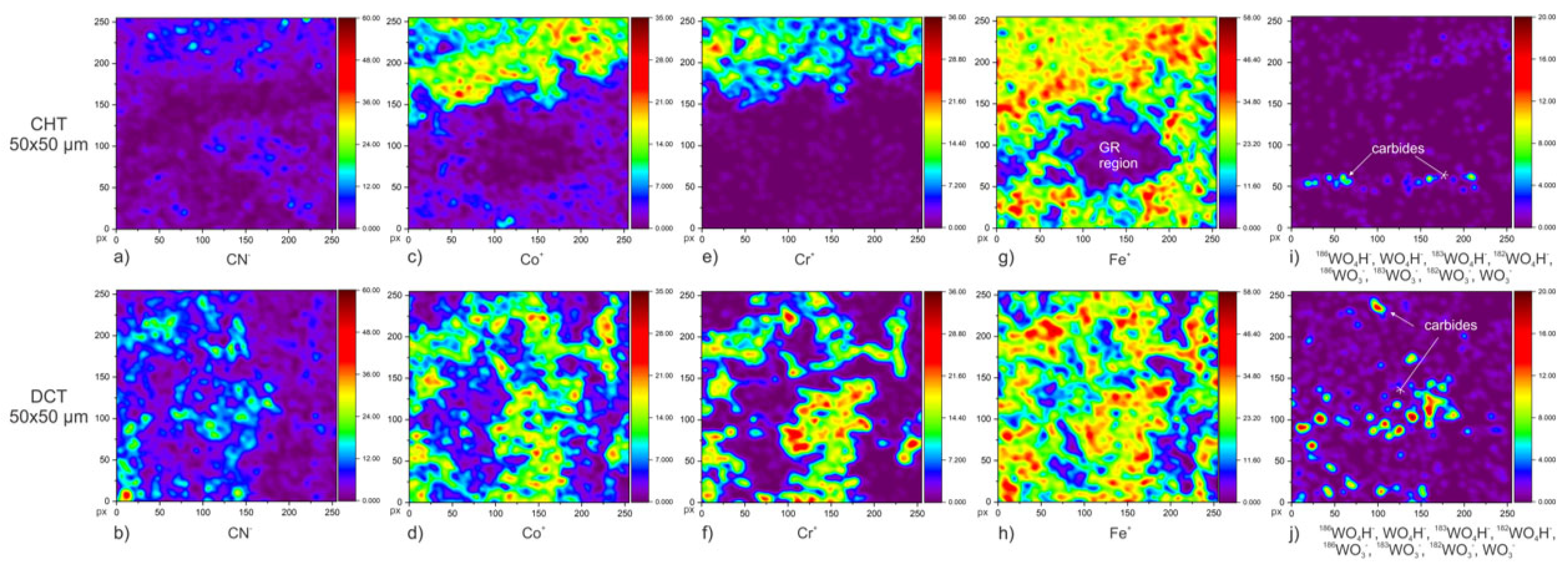
To provide a deeper insight into the newly observed surface chemistry dynamic of the passive film and ghost layer in correlation to GR in a DCT sample, ToF-SIMS surface analysis and in-depth profiling (Chapter 3.4) were carried out on CHT and DCT specimens after 1 day exposure in chloride-ions-enriched medium at room temperature (21 °C). The ToF-SIMS images were used to identify differences in the surface distribution of ionic species related to corrosion product and their development on the samples’ surface. The samples are assumed to be chemically and microstructurally homogenous and the corrosion products (oxide layer) and passive layer are homogeneously distributed on the sample surface. Nitrogen content (N) was measured with CN− signal, due to the small ionization yield of N with ToF-SIMS. To indirectly indicate the corrosion propagation of samples, the isotope behavior of Cl was tracked, as Cl is the element with highest electron affinity that can be present within the corrosion products. For this reason, the mapping of Cl− ion and its isotope variants 35Cl/37Cl were measured. Furthermore, to track the dynamics of other main alloying elements (C, Co, Cr, Fe, V and W), both negative and positive polarity measurements were performed. The species selected for each selected alloying element are: C (C−, CH−, C2−, C2H−, CHO2−, C2H2O2−), Cr (Cr+, CrOH−), Co (Co+, CoO−), Cl (Cl−), Fe (Fe+, 54Fe+, FeH+), N (CN−), V (V+, VO−), W (186WO4H−, WO4H−, 183WO4H−, 182WO4H−, 186WO3−, 183WO3−, 182WO3−, WO3−). Unfortunately, no Mo species could be detected for the description of Mo dynamics.
Figure 3,
Figure 4 and
Figure 5 show the results of low-magnification ToF-SIMS analysis of both polarities, presenting cumulative ion images of selected ion species for individual elements. The first image (
Figure 3a,
Figure 4a and
Figure 5a,b) presents the distribution of Cl
− ions, because it can indicate the passive film structure through its incorporation within the passive film and can possibly explain the breakdown dynamics [
36] of the “ghost layer” formed by DCT. The comparison of CHT (
Figure 3a) and DCT (
Figure 4a) samples clearly shows higher abundance of Cl
− ions for Cl of nitrides in CHT sample in the martensitic matrix of the sample. This provides one of the first pieces of direct evidence that DCT affects the passive film properties. The source of nitrogen for DCT is the immersion media from which the nitrogen adsorbs onto the surface and later diffuses during high-temperature treatment into the outermost layers of the material as interstitially dissolved. The nitrogen incorporation is considered to occur through vacancies and intergranular spacings that are present in the martensitic lattice. Moreover, this incorporation could be the primary mechanism, which is latter accompanied in different environments by the secondary mechanism of formation of NH
4+ ions. This results in electro-potential discharge [
37] of the newly formed “ghost layer” (passive layer) and reduced degradation of the material.
The next alloying element analyzed was cobalt (ion forms of Co
− and CoO
−),
Figure 3d,
Figure 4d and
Figure 5b–g. Compared to other alloying elements of the investigated alloy, cobalt is mainly present in the martensitic matrix in the form of a solid solution. When comparing both samples, CHT (
Figure 3d and
Figure 5c) and DCT (
Figure 4d and
Figure 5d), no significant difference in distribution or abundance could be observed (the spatial distribution of corrosion crust was taken into account). Chromium distribution (Cr
+ and CrOH
− forms);
Figure 3e,
Figure 4e and
Figure 5e,f, clearly indicates regions of carbides, which are the main source of chromium. However, from the maps and the corrosion crust analysis chromium was determined to not play a primary role in the corrosion resistance mechanism of the investigated alloy, neither for CHT nor DCT samples. This can be explained by the lower amount (4.10 wt.%) of chromium compared to stainless steels (>10 wt.%), for which Cr is the main contributor to the corrosion resistance. In the current case (AISI M35) cobalt in high content (4.52 wt.%) has a prevalent role in corrosion resistance over chromium [
38]. From this, and in general even distribution of Co, it is postulated that the underlying passive film is partially formed from cobalt. Nevertheless, the higher local presence of chromium in
Figure 5e,f indicates local pitting of the samples (evaluated in the next section), if not correlated to carbides. Similar relation of Cr with local pitting has been also observed in previous study with cross-sectional SEM investigation [
13].
Iron distribution was measured by Fe
+,
54Fe
+, FeH
+ ions (
Figure 3f,
Figure 4f and
Figure 5g,h). On one hand, the distribution of iron indicates the location of specific carbides when combined with other elemental maps (C, Cr, W). On the other hand, the absence of iron species in the corrosion crust indicates the presence and position of GR I+II (
Figure 5g,h and
Figure 6), when associated with the characteristic elements (Cl and S) of GR for CHT and DCT samples. The map distribution of vanadium (V
+, VO
− ions) in CHT (
Figure 3g) and DCT (
Figure 4g) samples show the peaks corresponding to the distribution of carbides in the matrix. Due to its concentration in the investigated alloy (2.01 wt.%), vanadium is not supposed to play an important role in the corrosion resistance of the samples. However, vanadium could theoretically help improve corrosion resistance by reducing both the formation of salt film and the formation rate of pits, as suggested by Ras et al. [
39]. The distribution of the most abundant (6.22 wt.%) alloying element, tungsten (
186WO
4H
−, WO
4H
−,
183WO
4H
−,
182WO
4H
−,
186WO
3−,
183WO
3−,
182WO
3−, WO
3− ions), shows localized concentrations, which correspond to carbides enriched by tungsten (M
6C [
33]), present in both CHT (
Figure 3h and
Figure 5i) and DCT (
Figure 4h and
Figure 5j) samples. No other significant information was obtained from tungsten distribution and its influence on corrosion resistance.
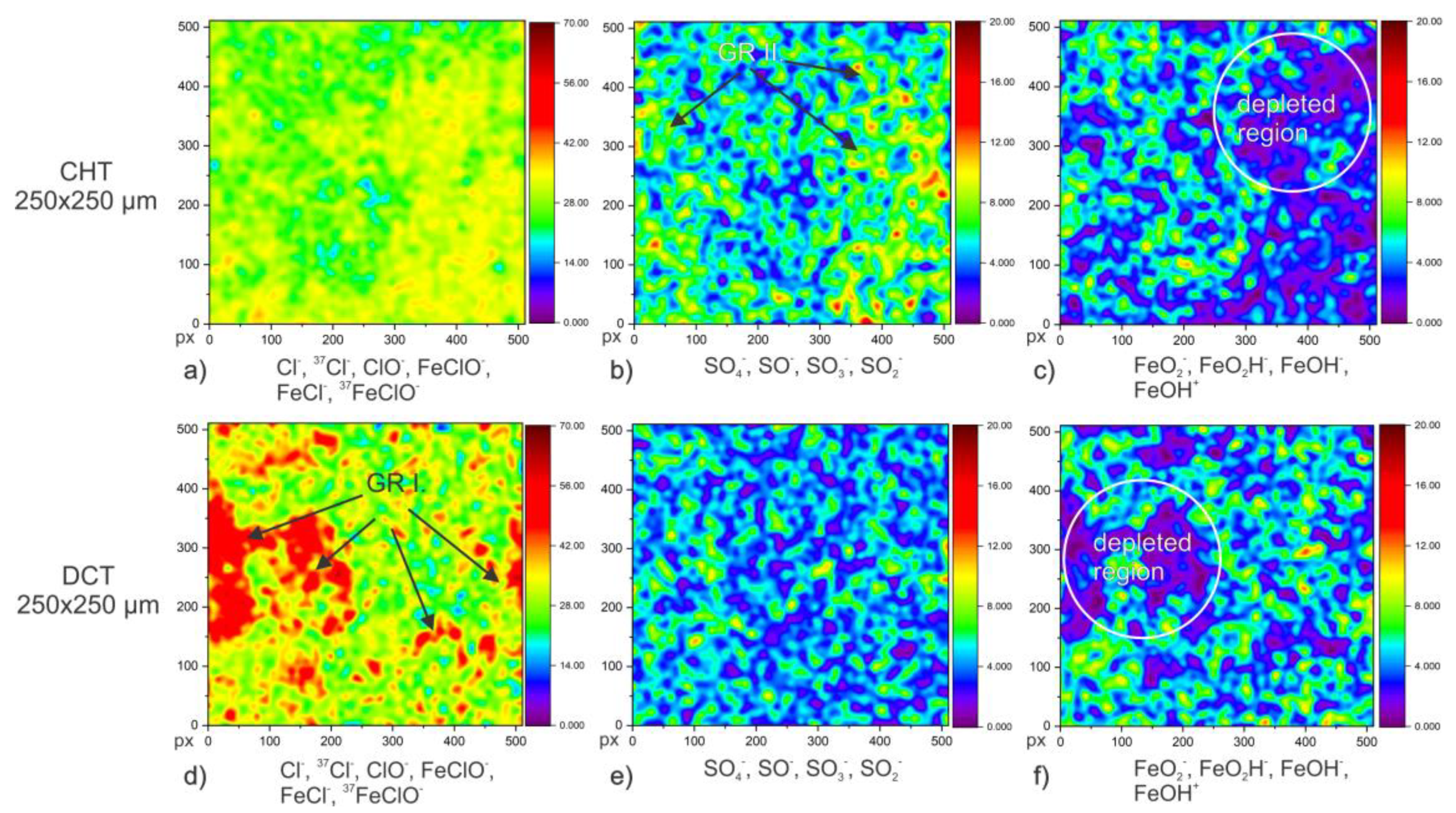
Figure 6 shows the distribution of green rust, type I (a,b) and type II (c,d), and Fe-oxides/hydroxides (e,f) on the samples surface. The ToF-SIMS analysis clearly shows the predominant formation of GR type I (combination of ions Cl
−,
37Cl
−, ClO
−, FeClO
−, FeCl
− and
37FeClO
−) in the DCT sample, whereas GR type II (combination of ions SO
4−, SO
−, SO
3− and SO
2−) has higher abundance in the CHT sample, corresponding well with XRD results (
Figure 1a). Absence or reduction of GR type II could not be linked to any improvement in corrosion resistance. Additionally, excessive presence of green rust was observed for the DCT sample compared to the CHT sample. The higher presence of GR for the DCT sample is associated with the increased concentration of nitrogen on the surface, which together with chlorine is the basis for the development of GR (excess amount of NO
3−, Cl
− and NH
4+ ions) [
40]. This confirms our previous observations [
13] and proposed theory that GR I plays an important role in the improvement of the corrosion resistance of the DCT sample. The proposed mechanism for improved corrosion resistance lies in the formation of GR I, as an inner part of the oxide layer formed over the passive layer. The GR I then acts as a buffer layer for the preferential development of magnetite, which is later covered by other Fe oxides/hydroxides as part of the oxide layer. Such a mechanism of GR preferential growth of magnetite was confirmed by Sumoondur et al. 2008 [
41]. The distribution of GR was additionally correlated and confirmed with Fe-oxides/hydroxides, as indicated in
Figure 6c,f.
3.4. ToF-SIMS Depth Profiling
ToF-SIMS depth profiling was performed with a negative ion charge. The ToF-SIMS depth profile analysis includes all corrosion products of the crust. The oxide layer is identified as the layer with an initial increase in oxides and hydroxides, which is defined as 0–2000 s of sputter time for the CHT sample and 0–1000 s for the DCT sample, respectively. The passive film is the region between the oxide layer and the metallic substrate, expressed as a second increase in the intensity of alloying elements (
Figure 7 and
Figure 8). The passive film for CHT is 2000–3200 s and for DCT, 1000–3800 s of sputtering time, respectively. The region of metallic substrate is defined as the region of rapid decrease in oxides/hydroxides presence and constant value of alloying elements, which starts for the CHT sample after 3200 s and for the DCT sample after 3800 s of sputtering (
Figure 7 and
Figure 8).
When comparing the ions CrO
−, VO
−, WO
3− and CoO
− in CHT (
Figure 7a) and DCT samples (
Figure 7b), a more constant distribution of alloying elements throughout the passive film is observed for DCT compared to CHT. Additionally, the ions in CHT sample (
Figure 7a) have higher intensity compared to DCT (
Figure 7b), in both the oxide layer and passive film. CrO
−, as a representative for chromium distribution, has its main peak at ~130 s for the CHT sample (
Figure 7a) and at ~100 s of sputtering for the DCT sample (
Figure 7b), followed by a continuous increase in intensity towards the metallic substrate. In addition to CrO
−, CrO
2− was also detected in the DCT sample, with its main peak at ~125 s and then a significant drop occurring within the oxide layer. This significant drop indicates the inner layer of the oxide film, which is the transition layer between the outer oxide layer and the passive film. A similar structure of the oxide film has been reported by other researchers [
42]. VO
− results show main peaks at ~125 s of sputtering for CHT (
Figure 7a) and ~25 s for the DCT (
Figure 7b) sample. Afterwards, the intensity drops towards the value of the metallic substrate. However, for the DCT sample a peak of VO
2− ions is also observed at ~20 s. Tungsten ion WO
3− signal shows a shift in the main peak of DCT to ~1750 s (
Figure 7b) compared to the CHT peak at ~1180 s (
Figure 7a). The results of CoO
−, provided main peaks at ~1050 s for CHT and at ~2010 s for DCT. In the DCT sample species, Co- was also observed with a main peak at ~3125 s. These results and the initial peaks, which form due to the matrix effect [
43] caused by oxide proximity, provide the correlation to the oxide thickness. The oxides for CHT are generally thicker and more enriched with the alloying elements Cr and V compared to DCT samples, which also correlates well with the ToF-SIMS spatial images and findings (
Figure 3 and
Figure 4). The distribution and ratio of ions is also different, especially within the passive film, which clearly indicates different dynamics of the passive film development for both samples.
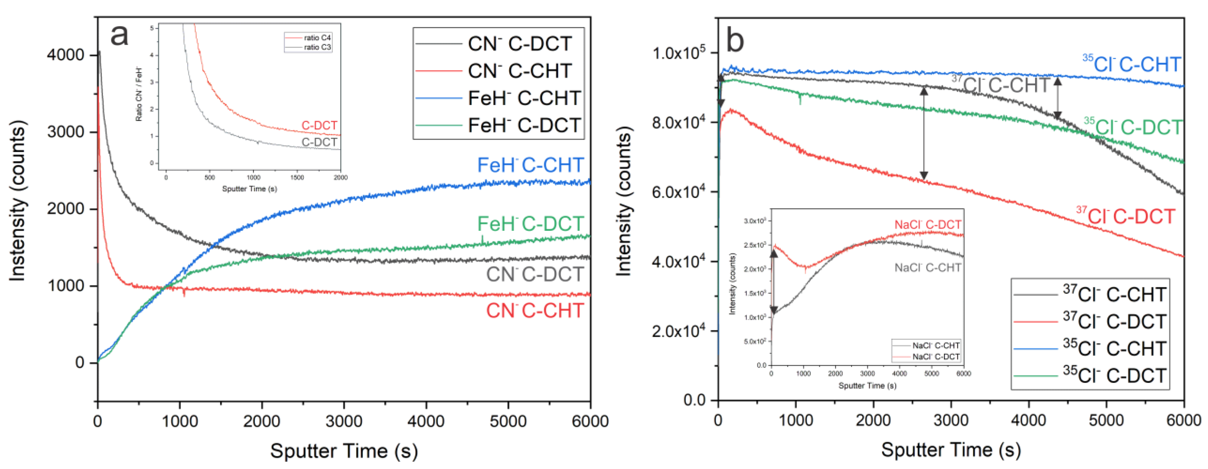
Considering the role of nitrogen in the DCT sample, the depth profile of CN
− and FeH
− was also analyzed. The CN
− profile (
Figure 8a) clearly shows a higher intensity of nitrogen in all surface layers (outer and inner layer of oxide film, and passive film) for the DCT sample compared to the CHT sample. In both cases the main peak is located at the beginning of the measurements. However, for the CHT sample a significantly stronger drop is present compared to DCT. The source of the nitrogen peak on the surface is related to the absorbed nitrogen and short-range diffusion from the quenching in nitrogen gas during heat treatment. However, for the DCT sample higher values of N below the material surface are a result of the DCT contribution, which is a consequence of the incorporation of nitrogen into the material during immersion into the liquid nitrogen. It is postulated that through boiling and bubbling and local high-pressure variations on the materials surface, the nitrogen is incorporated into the deeper portions of the material as well as adsorbed on the surface. Afterwards, during the heat treatment the surface-bounded nitrogen can diffuse deeper into the material due to the elevated temperatures of the tempering procedure (>600 °C). FeH
− was measured in order to determine the relative nitrogen presence within the iron matrix of both samples (
Figure 8a). The ratio of CN
−/FeH
− confirms the increased presence of nitrogen in the DCT sample. This clearly indicates that DCT has an important role in the surface chemistry of the selected alloy, which can be also implicated on other similar alloys, in bulk or thin film form, when treated with DCT. Furthermore, in order to observe the surface chemistry dynamics of oxide and passive film formation in correlation to GR, the spectra of
35Cl
−,
37Cl
− and NaCl
− were investigated. The depth profile shows lower signal of both isotopes
35/
37Cl in the DCT sample, as in the CHT sample. The main peaks of
35Cl
− and
37Cl
− are at ~315 and at ~245 s of sputtering for DCT and at ~285 and at ~235 s for the CHT sample, respectively. Another interesting dynamic was observed for NaCl
−. Beside the signal of NaCl
− for DCT being higher compared to the CHT sample, it drops after the initial peak and then slowly increases to its main peak at ~4810 s. This indicates the change in surface chemistry. For CHT a lower initial signal is observed, followed by an increase, with the main peak at ~2855 s, and then a drop in the signal, indicating less stable passive film formation of the CHT sample. The ratio between isotopes for each sample could possibly indicate the preferable GR formation in each sample. However, to obtain clear and reliable results, an isotope tracking method by introduction of stable oxygen isotopes should be applied and tested in future studies.
The results show that the reason behind the higher corrosion resistance of the DCT sample can be attributed to the protective nature of the DCT-induced passive film, which is composed of nitrogen and oxides/hydroxides of alloying elements (Cr, Co, V, W), on which the GR type I grows and acts as a precursor for magnetite and, later, other corrosion products. The results also indicate that the oxide layer and passive film for the DCT sample are thicker compared to the CHT sample, which additionally indicates that a more physically stable corrosion layer forms, and with it increased corrosion resistance when applying DCT.
3.5. Testing Effectiveness of Newly Characterized Passive Film Behavior for DCT-Treated High-Alloyed Ferrous Alloy
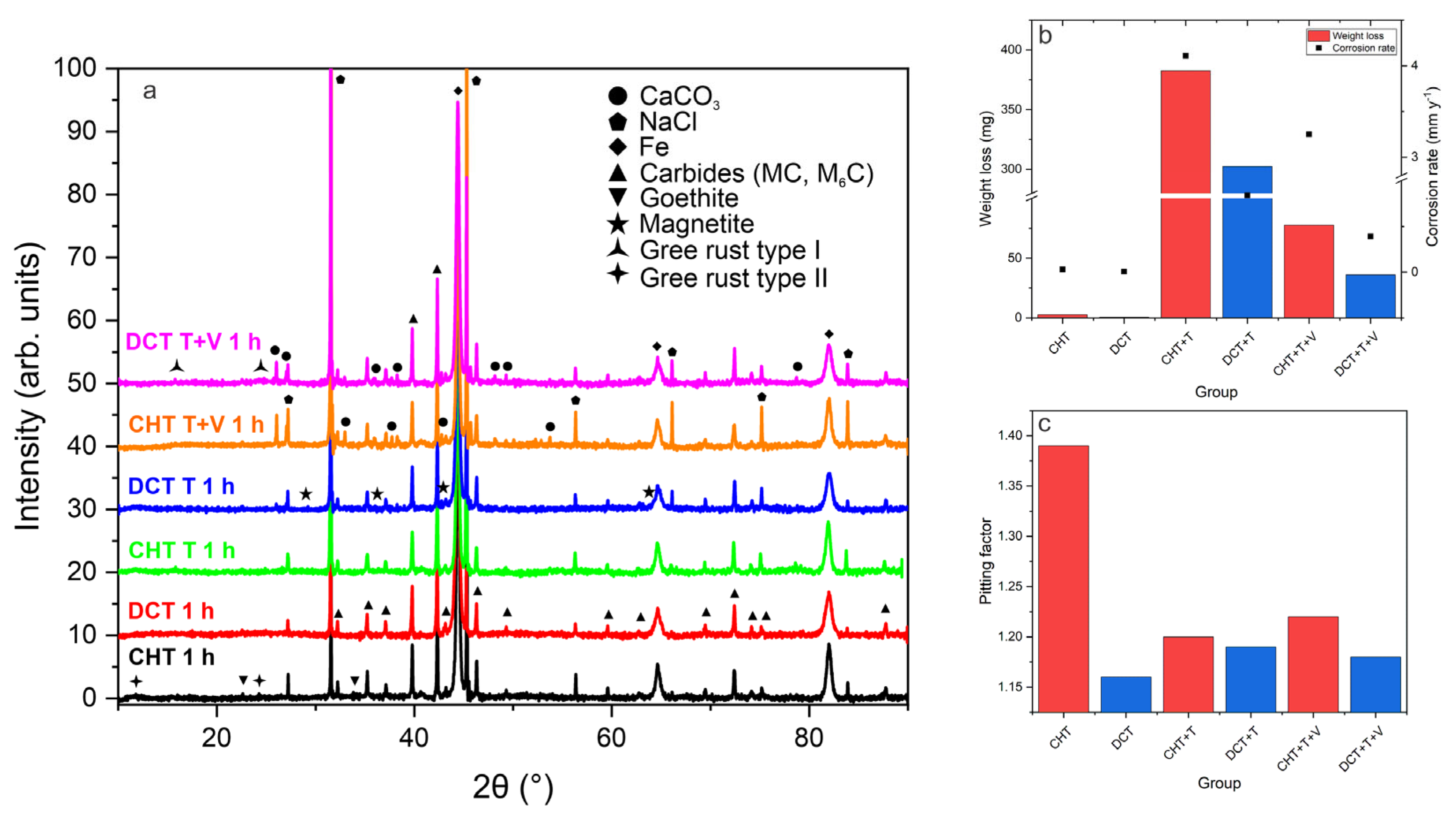
In order to test the stability of the newly observed passive film induced by DCT, three different environments were chosen for testing the hypothesis of higher stability of passive film. CHT and DCT samples were exposed to different environments (C-control environment, T-increased temperature of chloride-ions-enriched medium (100 °C) and T+V-increased temperature of chloride-ions-enriched medium (100 °C) and vibrations (25 Hz, 1 h). In the first step, the composition of corrosion products in all three environments was measured. The XRD data, presented in
Figure 9a, show the presence of different corrosion products. It is confirmed that for DCT, GR I forms after just 1 h of exposure, and this is observed for all three testing conditions, whereas GR II is mainly present in CHT samples and also forms after 1 h exposure in all conditions. The increased formation of magnetite can also be observed for DCT samples, compared to the CHT counterparts. Other corrosion products present in samples are calcium carbonate, halite, iron as matrix and goethite (
Figure 9a). In the second step, the weight loss of each sample group (10 samples per group) was measured in order to observe the difference in corrosion performance between DCT and CHT samples. The average weight loss (mg) after 1 h of exposure for all six testing groups is shown in
Figure 9b. In the control group (room temperature, standard conditions) the weight loss and corrosion rate of CHT and DCT was 2.6 ± 0.1 mg and 0.03 ± 0.001 mm/y, and 0.6 ± 0.01 mg and 0.006 ± 0.0005 mm/y, respectively. Under the second condition (elevated temperature; T), the weight loss increased due to the thermal influence on the corrosion propagation. Nevertheless, for the second condition the weight loss and corrosion rate were lower for DCT in comparison with CHT (CHT+T: 382.7 ± 5 mg and 4.11 ± 0.1 mm/y; DCT+T: 302.4 ± 3 mg and 0.84 ± 0.05 mm/y). Under the last condition with higher temperature and vibrations (T+V), the weight loss and corrosion rate for CHT and DCT samples are 77.7 ± 2 mg and 3.25 ± 0.1 mm/y, and 36 ± 2 mg and 0.39 ± 0.01 mm/y, respectively. In all three environments, the DCT samples display improved corrosion properties, which is clearly emphasized in conditions with a higher temperature. The data suggest that the DCT-induced passive film actively increases material corrosion resistance. The improvement in control environment is 75% in terms of weight loss and 80% in corrosion rate. In a high-temperature environment improvement is 20% and 79%, and in a high-temperature environment combined with vibrations it is 53% and 88%, respectively.
In order to test the stability of the newly observed passive film induced by DCT, three different environments were chosen to test the hypothesis of the higher stability of passive film. CHT and DCT samples were exposed to different environments (C-control environment, T-increased temperature of chloride-ions-enriched medium (100 °C) and T+V-increased temperature of chloride-ions-enriched medium (100 °C) and vibrations (25 Hz, 1 h). In the first step, the composition of corrosion products in all three environments was measured. The XRD data, presented in
Figure 9a, shows presence of different corrosion products. It is confirmed that for DCT GR I forms after just 1 h of exposure, observed for all three testing conditions. Whereas GR II is mainly present in CHT samples and also forms already after 1 h exposure in all conditions. The increased formation of magnetite can also be observed for DCT samples, compared to its CHT counterparts. Other corrosion products present in samples are calcium carbonate, halite, iron as matrix and goethite (
Figure 9a). In the second step the weight loss of each sample group (10 samples per group) was measured in order to observe the difference in corrosion performance between DCT and CHT samples. The average weight loss (mg) after 1 h of exposure for all six testing groups is shown in
Figure 9b. In the control group (room temperature, standard conditions) the weight loss and corrosion rate of CHT and DCT was 2.6 ± 0.1 mg and 0.03 ± 0.001 mm/y, and 0.6 ± 0.01 mg and 0.006 ± 0.0005 mm/y, respectively. Under the second condition (elevated temperature; T), the weight loss increased due to the thermal influence on the corrosion propagation. Nevertheless, for the second condition the weight loss and corrosion rate were lower for DCT in comparison to CHT (CHT+T: 382.7 ± 5 mg and 4.11 ± 0.1 mm/y; DCT+T: 302.4 ± 3 mg and 0.84 ± 0.05 mm/y). Under the last condition with higher temperature and vibrations (T+V), the weight loss and corrosion rate for CHT and DCT samples are 77.7 ± 2 mg and 3.25 ± 0.1 mm/y, and 36 ± 2 mg and 0.39 ± 0.01 mm/y, respectively. In all three environments, the DCT samples display improved corrosion properties, which is clearly emphasized in conditions with higher temperature. The data suggest that the DCT-induced passive film actively increases material corrosion resistance. The improvement in the control environment is 75% in terms of weight loss and 80% in terms of the corrosion rate. In a high-temperature environment the improvement is 20 and 79%, and in a high-temperature environment combined with vibrations it is 53 and 88%, respectively.


